The Law of Reflection
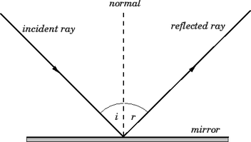
The law of reflection states that the incident ray, the reflected ray, and the normal to the surface of the mirror all lie in the same plane. Furthermore, the angle of reflection is equal to the angle of incidence.
Source: Farside.ph.utexas.edu,. 'Law Of Reflection'. N.p., 2015. Web. 9 Mar. 2015.
Source: Farside.ph.utexas.edu,. 'Law Of Reflection'. N.p., 2015. Web. 9 Mar. 2015.
Experiment 1
REFLECTION
- Single Ray
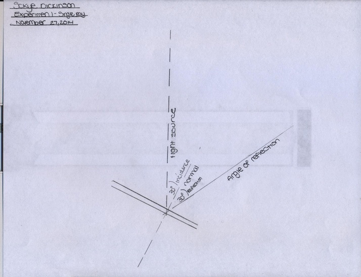
Project a single ray along the paper and mark its two ends. Place the plane mirror halfway along this path,
crossing it at an angle.
Mark the position of:-
• The glass front face of the mirror.
• The reflecting rear face of the mirror.
• The reflected ray (or rays). Explain the second fainter reflected ray.
Draw a line perpendicular to the mirror at the point where the incident and reflected rays meet the mirror
face. Such a perpendicular is called the NORMAL to the mirror at this point.
Measure the angle between the INCIDENT RAY and the NORMAL. This angle is called the ANGLE OF
INCIDENCE.
Measure the angle between the REFLECTED RAY and the NORMAL. This angle is called the ANGLE OF
REFLECTION.
These angles are measured from the NORMAL because in later experiments you will be reflecting rays
from curved mirrors. Since you cannot measure the angle between the ray and the curved surface of the
mirror, you must draw a normal to the curved surface and from this straight line measure the angles of
incidence and reflection.
REFLECTION
- Single Ray
Project a single ray along the paper and mark its two ends. Place the plane mirror halfway along this path,
crossing it at an angle.
Mark the position of:-
• The glass front face of the mirror.
• The reflecting rear face of the mirror.
• The reflected ray (or rays). Explain the second fainter reflected ray.
Draw a line perpendicular to the mirror at the point where the incident and reflected rays meet the mirror
face. Such a perpendicular is called the NORMAL to the mirror at this point.
Measure the angle between the INCIDENT RAY and the NORMAL. This angle is called the ANGLE OF
INCIDENCE.
Measure the angle between the REFLECTED RAY and the NORMAL. This angle is called the ANGLE OF
REFLECTION.
These angles are measured from the NORMAL because in later experiments you will be reflecting rays
from curved mirrors. Since you cannot measure the angle between the ray and the curved surface of the
mirror, you must draw a normal to the curved surface and from this straight line measure the angles of
incidence and reflection.
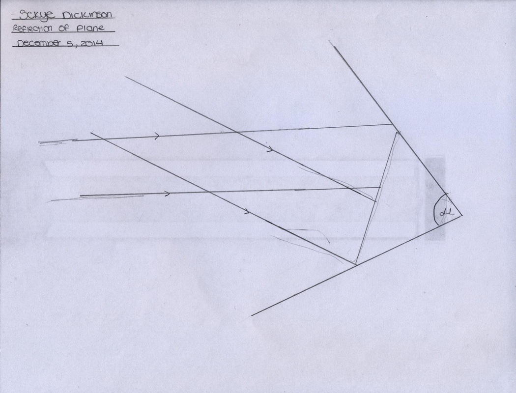
Experiment 2
REFLECTION
- Divergent Rays
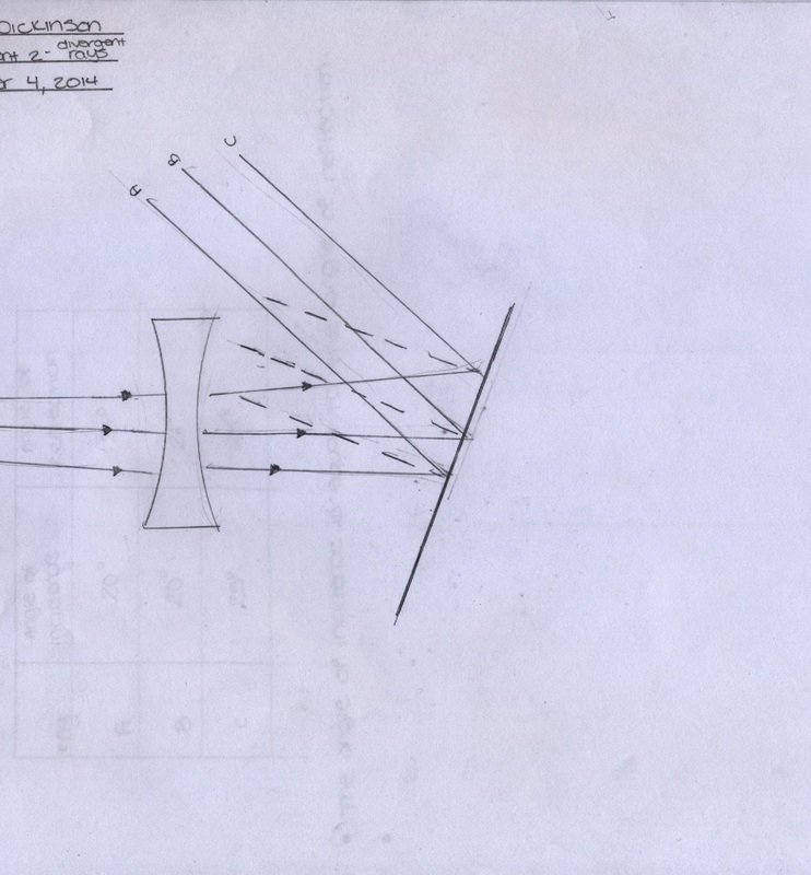
Place a triple slit former in the narrow front groove of the Light Box. Project a set of diverging rays along a
sheet of paper and mark the ray paths. Place a plane mirror so that the rays meet it at angles that are not
90o. Mark the reflecting surface of the mirror and the paths of the reflected rays.
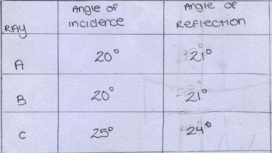
Is the angle of incidence greater than, less than, or equal to the angle of reflection?
QUESTIONS
• You have discovered one of the laws of reflection – what is it?
The angle of incidence is equal to the angle of reflection.
• Did the diverging rays remain diverging after reflection?
The diverging rays remain diverging after reflection.
• Do parallel rays remain parallel after reflection? Try it and see.
The rays will remain parallel after reflection only if it reflected on a smooth surface.
• Do converging rays remain converging after reflection? Try it and see.
Yes, converging rays remain converging after relection.
REFLECTION
- Divergent Rays
Place a triple slit former in the narrow front groove of the Light Box. Project a set of diverging rays along a
sheet of paper and mark the ray paths. Place a plane mirror so that the rays meet it at angles that are not
90o. Mark the reflecting surface of the mirror and the paths of the reflected rays.
Is the angle of incidence greater than, less than, or equal to the angle of reflection?
QUESTIONS
• You have discovered one of the laws of reflection – what is it?
The angle of incidence is equal to the angle of reflection.
• Did the diverging rays remain diverging after reflection?
The diverging rays remain diverging after reflection.
• Do parallel rays remain parallel after reflection? Try it and see.
The rays will remain parallel after reflection only if it reflected on a smooth surface.
• Do converging rays remain converging after reflection? Try it and see.
Yes, converging rays remain converging after relection.
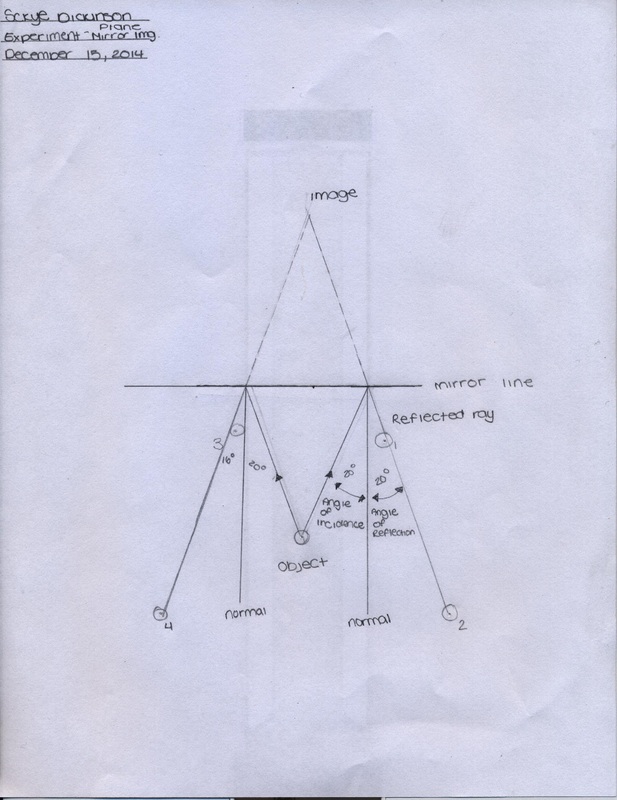
Experiment 4
REFLECTION
- Position in a Plane Mirror
When looking into a mirror, your reflected image appears to be somewhere behind the mirror. If you move
backwards half a metre, the reflection also moves away from you. The following experiment will help you
to locate the image position.
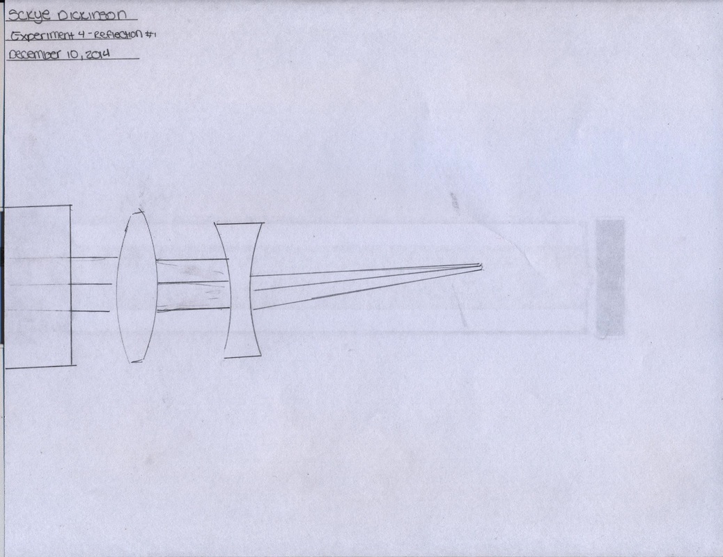
Project a set of converging rays across your sheet of paper and record their positions and focal point. Use
the lens combination shown and move them relative to one another to adjust your focal length.
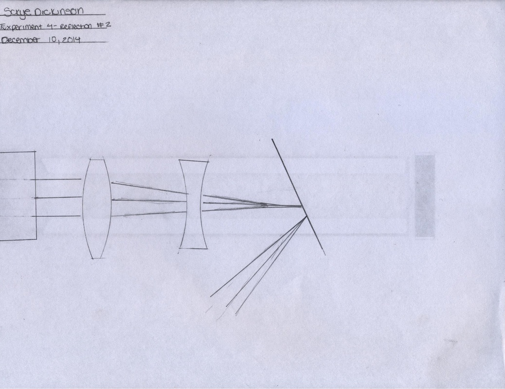
Place a plane mirror across the rays at an angle and record the paths of the reflected rays.
While looking in the mirror at the reflection of the converging rays, lift the mirror and observe the real
converging rays. Remove and replace the mirror several times vertically, noting the similarity of the real
and reflected rays.
• Would you say the point where the real rays meet is the reflection of the point where the reflected
rays meet?
Yes
Record these two points of convergence and the position of the reflecting surface of the mirror.
Draw a line joining the two points of convergence.
• What angle does the line make with the mirror?
40 Degrees
• What is the distance of the real convergence point and of the reflection convergence point from
the mirror?
44 Degrees
Repeat the experiment with another piece of paper, another set of converging rays and the mirror closer
to or further from the point of convergence.
Locate the convergence points and the mirror position, then draw lines and measure angles as before.
Stand a pin vertically in the paper (using cardboard beneath it) exactly at the two convergence points.
You now have a pin in front of the mirror and another pin hidden behind the mirror.
Lift the mirror vertically until you can see the hidden pin, then replace it and lift it several times.
• Is the hidden pin located at the position of the reflected image of the front pin?
Yes
• Does any shift in your (the observer’s) position affect the location of the image position?
Yes, some positions make the pins not visible.
Leave the front pin and the mirror unaltered. Try it and see.
REFLECTION
- Position in a Plane Mirror
When looking into a mirror, your reflected image appears to be somewhere behind the mirror. If you move
backwards half a metre, the reflection also moves away from you. The following experiment will help you
to locate the image position.
Project a set of converging rays across your sheet of paper and record their positions and focal point. Use
the lens combination shown and move them relative to one another to adjust your focal length.
Place a plane mirror across the rays at an angle and record the paths of the reflected rays.
While looking in the mirror at the reflection of the converging rays, lift the mirror and observe the real
converging rays. Remove and replace the mirror several times vertically, noting the similarity of the real
and reflected rays.
• Would you say the point where the real rays meet is the reflection of the point where the reflected
rays meet?
Yes
Record these two points of convergence and the position of the reflecting surface of the mirror.
Draw a line joining the two points of convergence.
• What angle does the line make with the mirror?
40 Degrees
• What is the distance of the real convergence point and of the reflection convergence point from
the mirror?
44 Degrees
Repeat the experiment with another piece of paper, another set of converging rays and the mirror closer
to or further from the point of convergence.
Locate the convergence points and the mirror position, then draw lines and measure angles as before.
Stand a pin vertically in the paper (using cardboard beneath it) exactly at the two convergence points.
You now have a pin in front of the mirror and another pin hidden behind the mirror.
Lift the mirror vertically until you can see the hidden pin, then replace it and lift it several times.
• Is the hidden pin located at the position of the reflected image of the front pin?
Yes
• Does any shift in your (the observer’s) position affect the location of the image position?
Yes, some positions make the pins not visible.
Leave the front pin and the mirror unaltered. Try it and see.
Experiment 6
REFLECTION
- Rotation of a Plane Mirror
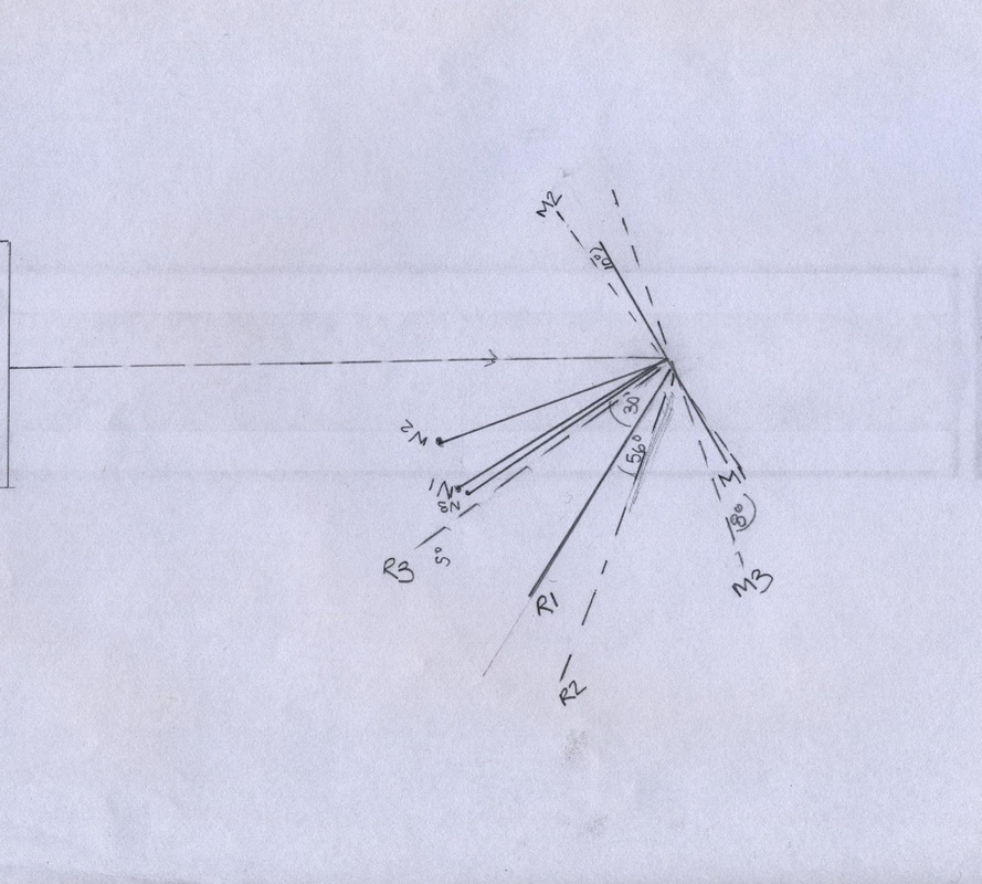
Aim a single ray of light at a plane mirror. Record the incident ray, the mirror reflecting surface position
(label it M1) and the reflected ray (label it R1).
Now rotate the mirror about 5o around the incident point, so that the incident ray strikes the mirror in the
same position, but at a slightly different angle.
Record the new mirror position as M2 and the new reflected ray as R2.
Using a protractor, measure the angle through which the mirror was rotated (the angle between lines M1
and M2).
Similarly measure the angle through which the reflected ray was rotated (the angle between lines R1 and
R2).
Compare the two angles.
• Predict what will happen to R2 if the mirror is rotated from M2 by a further 10o.
R2 will rotate with the movement of M2
Check if your prediction is correct.
This technique is often used by scientists to exaggerate or amplify slight movements within measuring
equipment such as electrical meters. Place the mirror in such a position that the reflected beam falls on a
wall or a sheet of card about two metres from the mirror.
Move the mirror fractionally by about 0.5o.
• What is observed at the distant image?
The distant image is smaller.
REFLECTION
- Rotation of a Plane Mirror
Aim a single ray of light at a plane mirror. Record the incident ray, the mirror reflecting surface position
(label it M1) and the reflected ray (label it R1).
Now rotate the mirror about 5o around the incident point, so that the incident ray strikes the mirror in the
same position, but at a slightly different angle.
Record the new mirror position as M2 and the new reflected ray as R2.
Using a protractor, measure the angle through which the mirror was rotated (the angle between lines M1
and M2).
Similarly measure the angle through which the reflected ray was rotated (the angle between lines R1 and
R2).
Compare the two angles.
• Predict what will happen to R2 if the mirror is rotated from M2 by a further 10o.
R2 will rotate with the movement of M2
Check if your prediction is correct.
This technique is often used by scientists to exaggerate or amplify slight movements within measuring
equipment such as electrical meters. Place the mirror in such a position that the reflected beam falls on a
wall or a sheet of card about two metres from the mirror.
Move the mirror fractionally by about 0.5o.
• What is observed at the distant image?
The distant image is smaller.
Experiment 8
REFLECTION
- In a Circular, Concave Mirror.
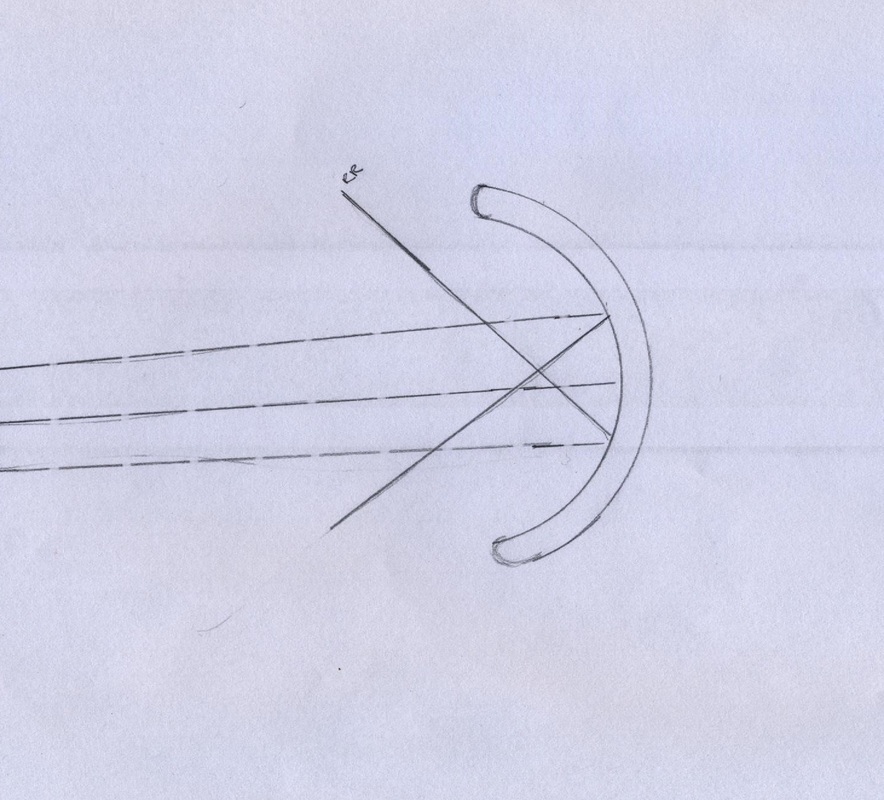
Select the semi-circular curved mirror.
Aim a set of parallel rays into the centre of the inside curve of the mirror so that the rays are parallel to the
axis of symmetry of the mirror.
Record the incident and reflected rays and note where they meet. This point is called the FOCUS of the
mirror.
• How far is the focus (or FOCAL POINT) from the mirror?
2 cm
This distance is called the FOCAL LENGTH of the mirror.
If the focal point appears blurred and broad, with too many rays overlapping through it, block the outer
rays as they leave the Light Box and use only the central ones.
REFLECTION
- In a Circular, Concave Mirror.
Select the semi-circular curved mirror.
Aim a set of parallel rays into the centre of the inside curve of the mirror so that the rays are parallel to the
axis of symmetry of the mirror.
Record the incident and reflected rays and note where they meet. This point is called the FOCUS of the
mirror.
• How far is the focus (or FOCAL POINT) from the mirror?
2 cm
This distance is called the FOCAL LENGTH of the mirror.
If the focal point appears blurred and broad, with too many rays overlapping through it, block the outer
rays as they leave the Light Box and use only the central ones.
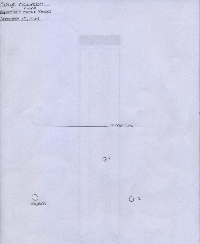
Reflection of light
When the 3 pins were placed correctly, it looked like it was only 1 pin in the mirror.
Reflection of a plane Mirror
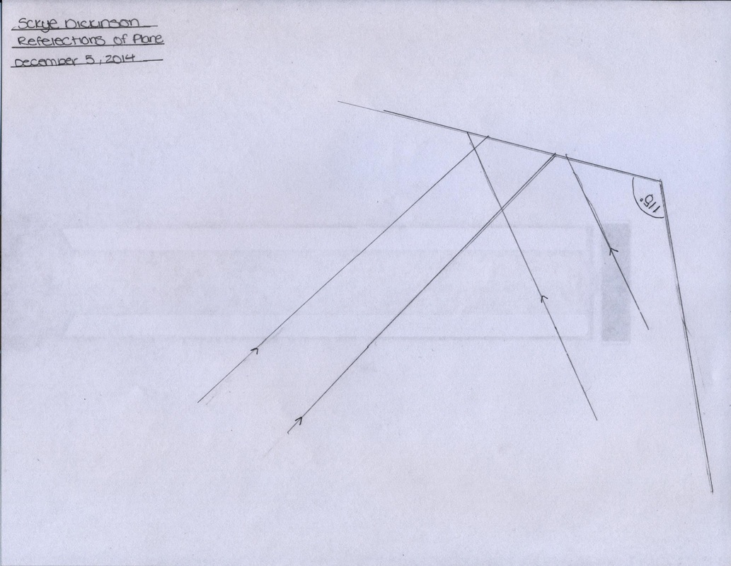
The reflection of light from a plane mirror can be summarised by the following laws:
1. The angle of incidence (i) is equal to the angle of reflection (r)
2. The incident ray, reflected ray and the normal to the surface at the point of incidence all lie in the same plane.
There are two types of images that can be projected.
- Real Images
a real image is an image which is located in the plane of convergence for the light rays that originate from a given object)
- Virtual Images
a virtual image is an optical image formed from the apparent divergence of light rays from a point, as opposed to an image formed from their actual divergence.
Source: Definition by Google
Plane Mirror Image
 RSS Feed
